


Structural Steel Fundamentals: Definitions and Material Classification
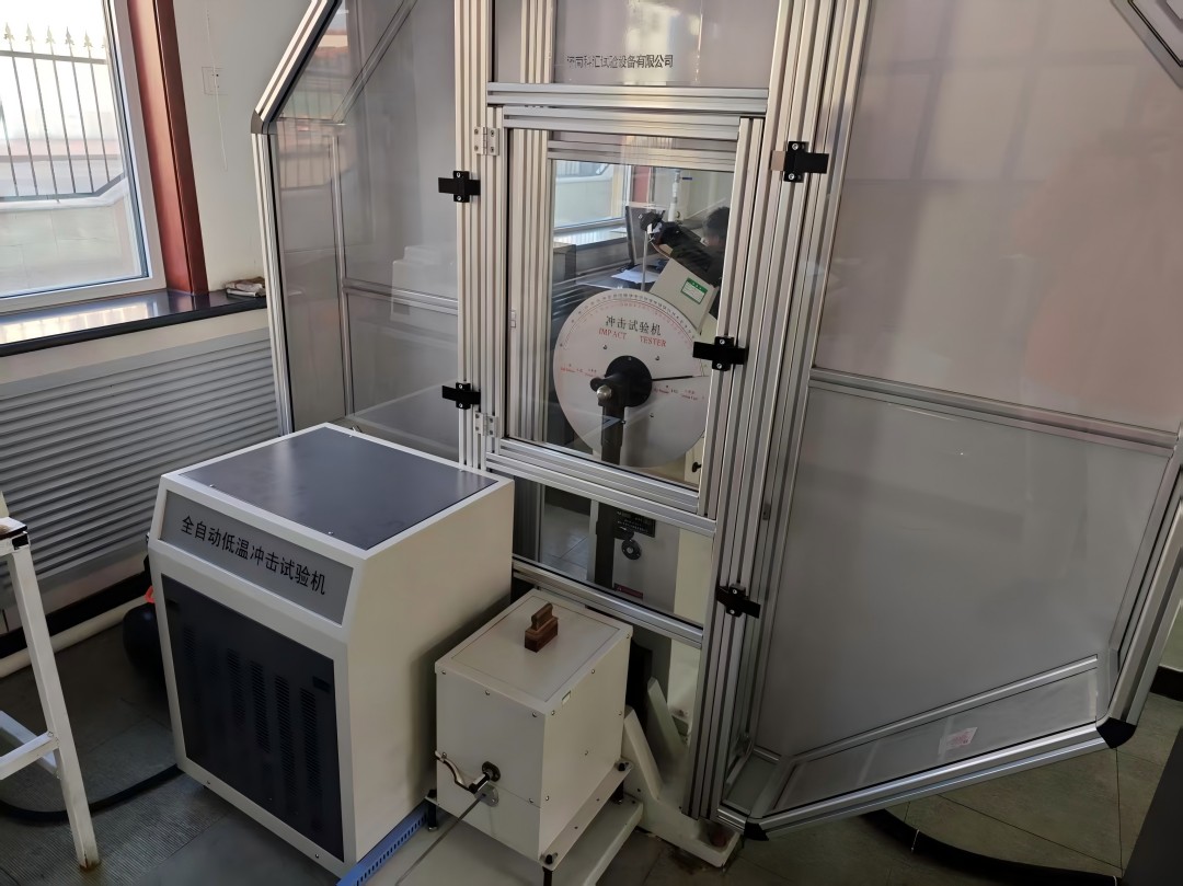
Structural steel represents a high-strength iron-carbon alloy engineered for load-bearing applications, defined by controlled chemical composition (typically 0.15%-0.30% carbon) and standardized mechanical properties. Classification systems categorize structural steels based on yield strength (ranging from 250 MPa to 690 MPa), ductility (minimum 18% elongation), and weldability, as stipulated in ASTM A36/A572 and EN 10025 specifications. Distinct from plain carbon steels, structural grades incorporate alloying elements such as manganese (up to 1.65%) and silicon (up to 0.40%) to optimize strength-to-weight ratios while maintaining fracture resistance under dynamic loading conditions.
Key technical features:
- Material standardization follows international codes governing:
-
Minimum yield strength thresholds
-
Charpy V-notch impact values
-
Carbon equivalent formulas (CEV ≤ 0.45% for weldability)
-
- Primary alloying mechanisms:
-
Manganese enhances hardenability and hot-rolling characteristics
-
Silicon improves deoxidation during steelmaking
-
Microalloying with vanadium/niobium enables thermomechanical strengthening
-
- Product forms comply with dimensional tolerances per:
-
-
ASTM A6/A6M (structural shapes)
-
EN 10034 (I-beam flange inclination limits)
-
JIS G3192 (H-section dimensional standards)
-
This metallurgical engineering framework ensures consistent performance across seismic-resistant building frames, long-span bridge trusses, and heavy industrial structures, balancing tensile capacity with deformation tolerance through controlled phase transformations in the steel microstructure.
Material Classification System
Structural steel classification follows a hierarchical system:
- Strength Grades (e.g., S235–S550 in EN standards);
- Alloy Subtypes (weathering steels, fire-resistant steels);
- Application-Specific Categories (bridge steels, seismic-resistant steels). Advanced variants include thermomechanical rolled (TM) steels for refined grain structures and high-strength low-alloy (HSLA) steels to minimize material thickness. This taxonomy ensures compliance with structural integrity requirements for vertical construction (high-rises), horizontal infrastructure (bridges), and industrial facilities (power plants).
The classification framework integrates metallurgical testing protocols—Charpy V-notch impact testing for toughness evaluation, Brinell hardness measurements, and spectrochemical analysis for elemental verification. Such rigor aligns material selection with project-specific stresses, environmental exposures (marine, seismic zones), and fabrication methods (bolted vs. welded connections), establishing a foundation for subsequent manufacturing and design phases.
Key Technical Enhancements:
-
TM Steels: Achieve 20–30% higher yield strength through controlled rolling and cooling, optimizing grain boundary refinement.
-
HSLA Grades: Reduce structural weight by 15–25% via microalloying with niobium/vanadium (0.05–0.15%), maintaining weldability.
-
Weathering Steels: Form protective patinas (FeOOH·nH₂O) under cyclic wet/dry conditions, eliminating need for coatings in moderate-corrosion environments (C3 per ISO 9223).
This systematic approach ensures traceable material performance from mill certification to field implementation, critical for code-compliant structural systems.
 |
 |
 |
 |
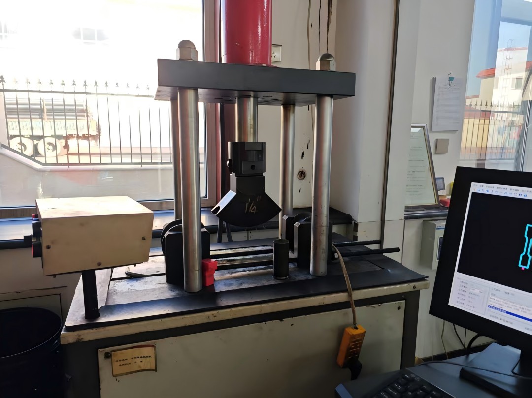 |
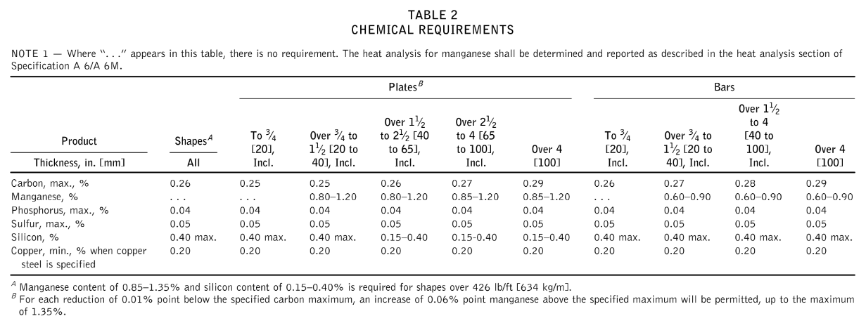
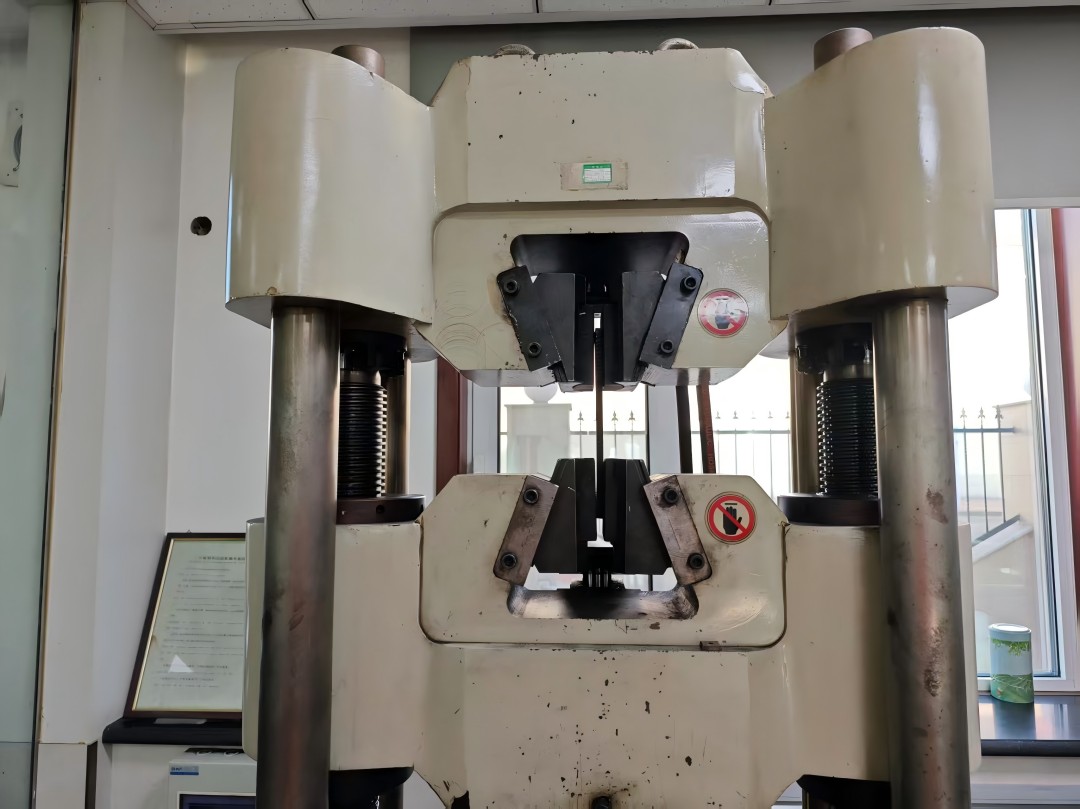
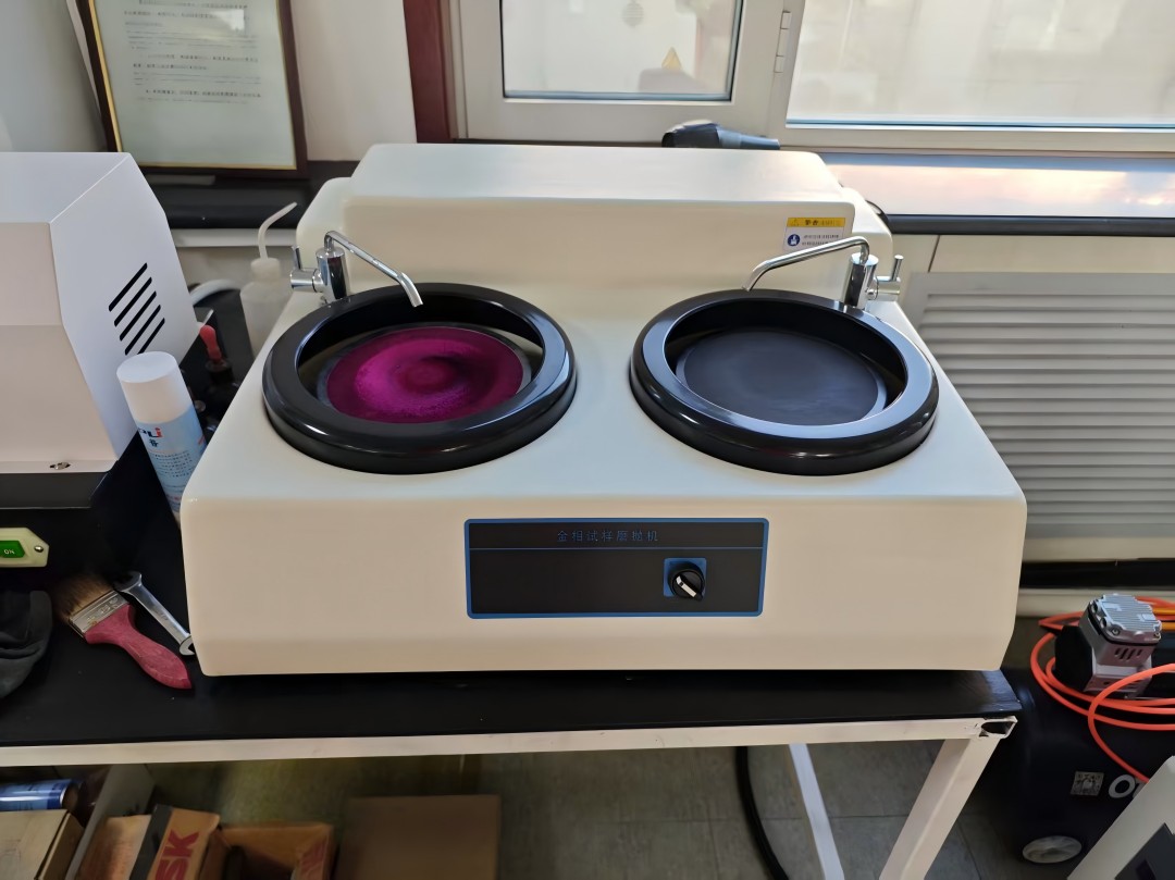
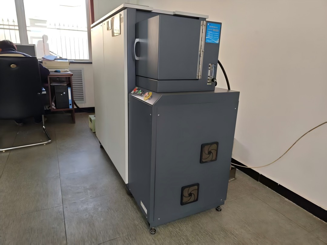
| 拉伸测试 | 金相实验 | 冲击测试 | 元素分析 | 弯曲测试 |
Manufacturing Processes:
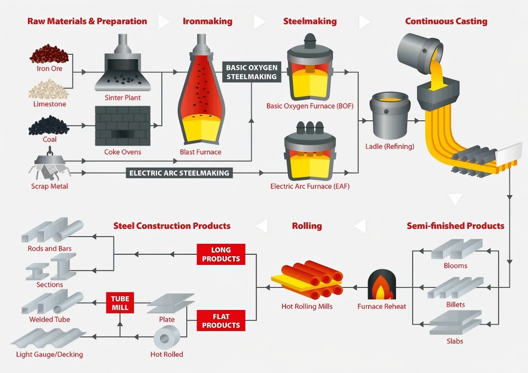
Metallurgical Production Techniques and Differentiation from Carbon Steel Alloys
Structural steel manufacturing employs advanced metallurgical processes, beginning with iron ore reduction in blast furnaces to convert raw materials into molten pig iron (3–4.5% carbon content). This primary material undergoes decarburization in basic oxygen furnaces (BOF) or electric arc furnaces (EAF), reducing carbon levels to 0.15–0.30% while introducing controlled manganese (0.90–1.60%) and silicon (0.15–0.40%) additions. Continuous casting technology is then applied to form standardized blooms/slabs, followed by thermomechanical controlled processing (TMCP)—hot rolling at 1,100–1,300°C to refine grain structures, achieving yield strengths up to 690 MPa. Post-rolling treatments such as quenching and tempering (Q&T) or normalization further enhance ductility and weldability while complying with ASTM A6/A6M dimensional tolerance requirements.
Key Differentiators from Carbon Steels:
-
Alloy Precision: Structural steels maintain strict Mn/Si ratios (±0.05%) versus carbon steels’ broader tolerances (±0.15%).
-
Microstructural Control: TMCP achieves ASTM grain size 8–12 compared to carbon steels’ typical 5–7.
-
Phase Optimization: Q&T creates tempered martensite with 22–25% improved impact toughness over carbon steels’ ferrite-pearlite matrix.
This process chain ensures structural steels outperform conventional carbon steels in critical metrics: 40% higher strength-to-weight ratios, 50% greater fatigue limits, and enhanced crack propagation resistance (ΔK_th ≥ 9 MPa√m).
The key differences between structural steel and ordinary carbon steel are threefold:
- Alloy Design – Structural grades use precise microalloying elements (such as vanadium and niobium) for precipitation hardening.
- Process Control – Strict adherence to the toughness requirements of EN 10025-2 (Charpy impact value at –50°C).
- Certification – Mandatory mill test reports to verify chemical and mechanical properties.

Standard carbon steels (e.g., SAE 1018) prioritize machinability by allowing higher sulfur/phosphorus content (≤0.05%), whereas structural steels reduce impurities (S≤0.025%, P≤0.025%) to prevent hot brittleness and cold cracking. This engineering optimization enables structural variants to withstand cyclic loads (up to 10^6 fatigue cycles) and seismic forces (R=8 response modification factor) that traditional steels cannot endure.
This difference is also reflected in lifecycle performance: Structural steels employ protective metallurgical techniques, such as the copper patina formation in ASTM A588 weathering steel (copper-platinum-chromium-nickel alloying), which improves corrosion resistance by 2-8 times compared to unprotected carbon steel.
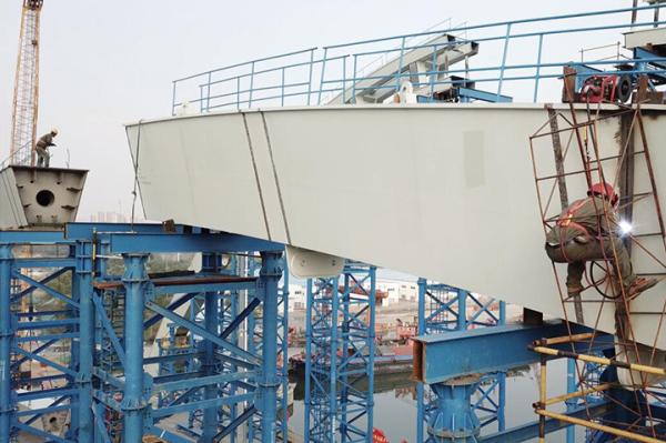
Engineering Applications:
Load-bearing frames in civil and industrial buildings


Industrial facilities utilize the spanning capability of steel structures (with clear spans up to 120 meters) to build refinery pipe racks and aircraft hangars, using ASTM A588 weathering steel to resist corrosive chemical vapors (with pH values ranging from 2 to 12). Modular bolted connections (complying with AISC 358 standards) facilitate equipment reconfiguration, while galvanized coatings (275 grams per square meter of zinc) ensure a 50-year service life for coastal power plants. Critical infrastructure, such as liquefied natural gas (LNG) storage tanks, uses low-temperature grade steels (EN 10028-4) to maintain ductility at temperatures as low as –165°C.
Bridge engineering utilizes the fatigue resistance of steel structures (with a durability of 10^7 cycles at a stress range of 100 MPa) to construct suspension spans and orthotropic decks. The steel structure of the Millau Viaduct stretches over 2460 meters, with piers reaching 270 meters in height, and uses S460ML thermomechanically rolled steel plates. It is optimized for vibrations caused by wind, with an amplitude of less than 0.15g. Accelerated Bridge Construction (ABC) techniques employ prefabricated steel box girders (EN 1090-2 EXC4 tolerances), reducing on-site construction time by 60%, while the monolithic pier design eliminates expansion joints in railway bridges exposed to temperature cycles between –40°C and +60°C.
Architectural Applications:
High-Rise Buildings, Industrial Facilities, and Bridge Superstructures
The unmatched versatility and strength of steel structures make them the cornerstone of modern architectural innovation. In high-rise buildings, the high strength-to-weight ratio of steel enables engineers to design skyscrapers exceeding 800 meters, such as the Burj Khalifa. The reinforced concrete core and leg systems help offset 30-50% of wind sway. Advanced steels, such as ASTM A992 (yield strength of 345 MPa), optimize column efficiency, reduce floor-to-floor height, and support vertical loads up to 25,000 kN. Modular steel frames enable rapid construction at a pace of 3-4 floors per week, and combined with composite flooring (steel deck + concrete), they achieve a 2-hour fire resistance rating without the need for bulky materials.
Industrial buildings leverage steel’s adaptability to complex geometries and harsh environments. Petrochemical plants use galvanized A36 steel frames to resist H2S corrosion (with an annual loss ≤0.5 mm), while aerospace facilities employ 120-meter clear-span steel trusses to protect aircraft assembly lines. Critical infrastructure, such as nuclear containment shells, use SA738 Grade B steel plates to withstand internal pressures of 70 MPa and radiation-induced embrittlement. Smart manufacturing technologies, such as laser-scanned bolt hole alignment (with precision of ±0.5 mm), ensure seamless integration of conveyor systems and robotic machinery.
In bridge engineering, steel structures enable record spans and adaptive designs. Cable-stayed bridges, such as the Russky Island Bridge in Russia, use S355J2W+N weathering steel arches with spans of up to 1,104 meters, protected by a copper patina layer to resist salt spray corrosion. Compared to concrete, isotropic steel bridge decks reduce dead load by 40%, which is crucial for movable bridges like the Tower Bridge in London, where a hydraulic system can rotate the 1,000-ton steel base in 90 seconds. Emerging applications include 3D-printed steel nodes for pedestrian bridges designed using topology optimization, saving 20% of material while maintaining EN 1090-2 Class C fatigue performance. These applications collectively demonstrate that steel structures are not only engineering solutions but also driving forces in architectural development.
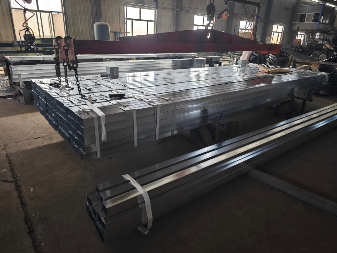
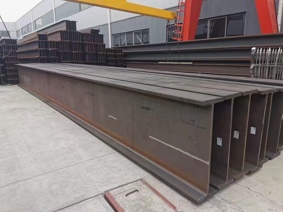
Standard Structural Profiles:
I-Beams (W Shape) – Click to view dimensions
ASTM A6/A36 certified wide flange beams (W8x31-W44x335) optimize load distribution through their H-shaped cross-section. With flange widths up to 16 inches and web thickness ranging from 0.3 to 4 inches, these beams are primarily used in high-rise building moment-resisting frames (bending modulus ≥1500 cm³) and bridge girders, with span-to-depth ratios of up to 20:1. Hot-rolled production ensures a dimensional tolerance of ±2 mm, while W14x132 fire-resistant profiles maintain a 2-hour fire rating at 650°C.
Angle Steel (L Shape) – Click to view dimensions
ASTM A36/A572-50 grade equal/unequal angle steel provides a yield strength of 360 MPa for support systems and equipment brackets. Cold-formed profiles (EN 10056-1) feature a radius of 5 mm and are weldable, while galvanized L4x3x3/8 profiles have a coating thickness of 610 g/m², making them suitable for coastal transmission towers. These are critical for truss connections, transmitting axial loads up to 900 kN through M24 bolt connections.
Steel Plates – Click to view dimensions
ASTM A36/A514 quenched and tempered plates (thickness from 6 mm to 300 mm) are used as shear walls and blast barriers, with a Charpy V-notch toughness of ≥27J at –20°C. Tread plates (ISO 9013) are used for wind turbine flange manufacturing (outer diameter: 8 m, flatness ±1.5 mm), while AR400 wear-resistant plates extend the lifespan of mining chutes by 300%. Plasma-cut through parts maintain ±0.8 mm accuracy and are used for nuclear reactor vessel manufacturing.
C-Channels (C-Purlins)
C3x5-C15x50 channels (ASTM A588 Corten steel) form the lower structure of roofs (span ≤9 meters) with a yield strength of 345 MPa and a corrosion rate of 0.25 mm/year. Roll-formed 200 mm deep sloped channels (EN 10346) with wind resistance of 12 kN/m integrate with mixed-section Z-frame structures for mezzanine floors in warehouses. Manufacturing includes pre-punched 22 mm bolt holes at 600 mm centers (complying with BS 5950 standard), reducing on-site assembly time by 40%.
 |
 |
 |
 |
 |
 |
Comparative Analysis: Structural Advantages vs. Thermal/Corrosion Limitations

Structural steel’s excellent strength-to-weight ratio (yield strength up to 690 MPa) and ductility (elongation ≥18%) allow for cost-effective long-span designs, reducing foundation loads by 30-50% compared to concrete. However, its thermal stability becomes important at temperatures above 540°C, where the modulus of elasticity decreases by 50%, requiring fire protection systems such as intumescent coatings (up to 2 hours at 1,000°C). Vulnerability to corrosion in chloride-rich environments (0.1-2 mm loss per year) necessitates protective measures – hot dip galvanizing (500 g/m2 zinc) or weathering steel alloys (ASTM A588, 2-4 times corrosion resistance). Modern engineering balances these trade-offs with hybrid systems, such as steel-concrete composites, and advanced coatings to achieve 75+ years of service life in harsh environments.
Service Life Parameters:
Atmospheric Corrosion Rates and Protective Coating Effectiveness
The atmospheric corrosion rate of structural steel varies significantly across different environments: industrial areas (0.05-0.15 mm/year due to sulfur dioxide emissions), coastal regions (0.1-0.8 mm/year due to chloride deposition), and rural areas (<0.03 mm/year). ISO 9223 classifies corrosivity (C1-C5), with offshore platforms (CX class) experiencing corrosion loss of up to 1.2 mm/year in splash zones. Predictive models like ISO 12944-2 correlate steel thickness loss with annual salt deposits (e.g., 300 mg/m²/day in marine environments), guiding material selection to achieve a design life of 25-50 years.
Protective coatings prevent degradation through multilayer systems: hot-dip galvanizing (85 μm of zinc, with a service life of 20-70 years in C3 environments) and epoxy-polyurethane hybrid coatings (250 μm DFT) can meet ISO 12944 C5-M durability standards. Advanced solutions like thermal spray aluminum (TSA, 150-200 μm) provide over 40 years of protection in tidal zones, while graphene-enhanced coatings inhibit under-film corrosion, with a corrosion rate of ≤0.001 mm/year. Regular inspections using DFT measurement devices (±10% accuracy) and electrochemical impedance spectroscopy ensure coating integrity, which is crucial for offshore wind turbines and highway bridges exposed to wet-dry cycling conditions.
Corrosion Mechanisms:
Oxidation Process in Urban/Coastal Environments
In urban environments, the corrosion of structural steel is caused by sulfur dioxide (SO₂) emissions (≤50 μg/m³), which react with atmospheric moisture to form sulfuric acid (pH 3-5), accelerating electrochemical oxidation at a rate of 0.05-0.15 mm/year. Wet-dry cycling conditions create varying aeration pools, concentrating pitting corrosion at welds and joints (depth increment ≤0.3 mm/year). Particulate matter (PM2.5) deposition further catalyzes localized electrochemical corrosion, particularly on defects such as mill scale on carbon steel surfaces.
Coastal corrosion is exacerbated by chloride ion deposition (10-500 mg/m²/day), where FeCl₂ intermediate products hydrolyze to form HCl, maintaining a self-catalytic rusting cycle. Salt spray can penetrate protective oxide layers (Fe₃O₄/γ-FeOOH), triggering under-film corrosion at relative humidity levels greater than 60%. The tidal zone is the most challenging, with mechanical erosion caused by splash (wear loss ≤0.8 mm/year) and cathodic delamination in submerged zones. ASTM G50-10 simulated tests confirm that unprotected steel in marine environments deteriorates within 7-15 years, while a dual coating system (epoxy + polyurethane) can extend service life to over 40 years.
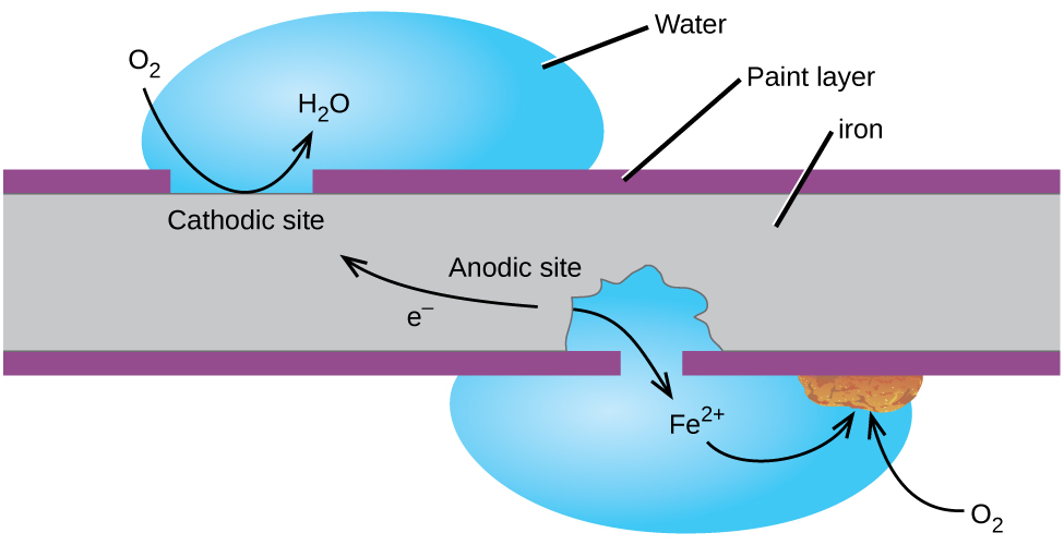
生锈原理
Production documentation:
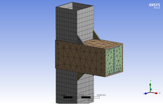
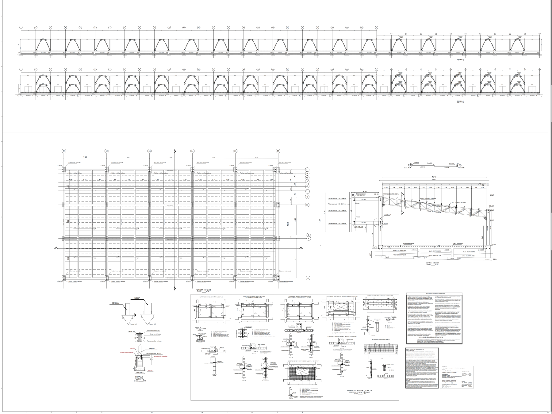
BIM-based shop drawings and connection detailing standards
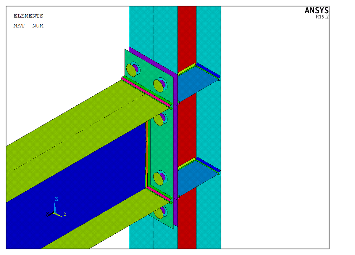
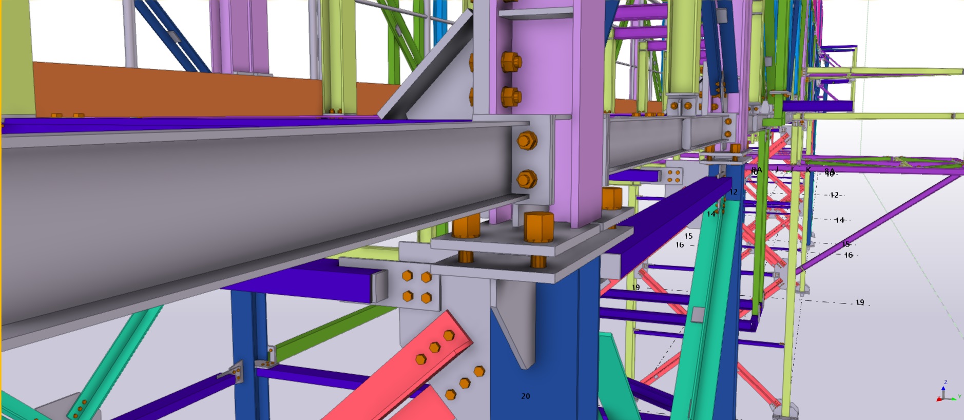
BIM-based shop drawings revolutionize steel fabrication by combining 3D parametric modeling (LOD 400+) with clash detection algorithms to achieve ±1.5mm dimensional accuracy in complex assemblies. Software platforms such as Tekla Structures automatically generate bolt hole patterns (AISC 303-22 compliant) and weld symbols (AWS A2.4 compliant), reducing drawing errors by 70% compared to manual CAD workflows. The models are synchronized with CNC machines in CIS/2 or IFC format, allowing direct fabrication of curved beams (radius ≥5m) and perforated plates (hole tolerance ±0.5mm).
Connection details comply with AISC 358 seismic provisions, specifying pre-qualified moment connections (RBS, T-tubes) and slip-critical bolted connections (ASTM F3125 Grade A325, preloaded to 70% of proof load). Critical joints require finite element analysis (FEA) verification of stress concentrations to ensure a 2:1 factor of safety at ASCE/SEI 7-22 load combinations. Field weld symbols follow AWS D1.8 for fracture-critical members, which mandates UT/MT testing (100% radiographic inspection) of full penetration groove welds.
Digital Collaboration Protocol (ISO 19650-3) manages cloud-based marking, tracking revision history across stakeholders. For EN 1090-2 EXC4 projects, shop drawings must demonstrate material traceability (heat number mapping) and surface finish (Sa 2½ blast profile). This BIM-to-fabrication workflow reduced RFI by 50% and achieved on-time delivery of 30 tons of steel modules with bolt hole alignment accuracy of ≤ 2 mm over a 100 meter span.
 |
 |
 |
 |
Surface Treatment Procedures:
Sandblasting, Zinc Primer, and Epoxy Coating Systems
Pre-treatment Phase (Removal of Oils/Contaminants)
Common Product Issue:
Residual mill oil (>50 mg/m²) on the web of I-beams reduces the adhesion of zinc primer (ASTM D4541 <3 MPa tensile strength).
Root Cause:
Oil penetrates beneath the mill scale, hindering the effectiveness of solvent wiping.
Solution:
-
Use an alkaline degreaser (pH 11-12) at a temperature of 80°C, with a spray cycle of 20 minutes.
-
Install an infrared drying zone (120°C × 15 minutes) to volatilize hydrocarbons.
-
Perform Bresle testing (ISO 8502-6) to detect soluble salts ≤3 mg/m².
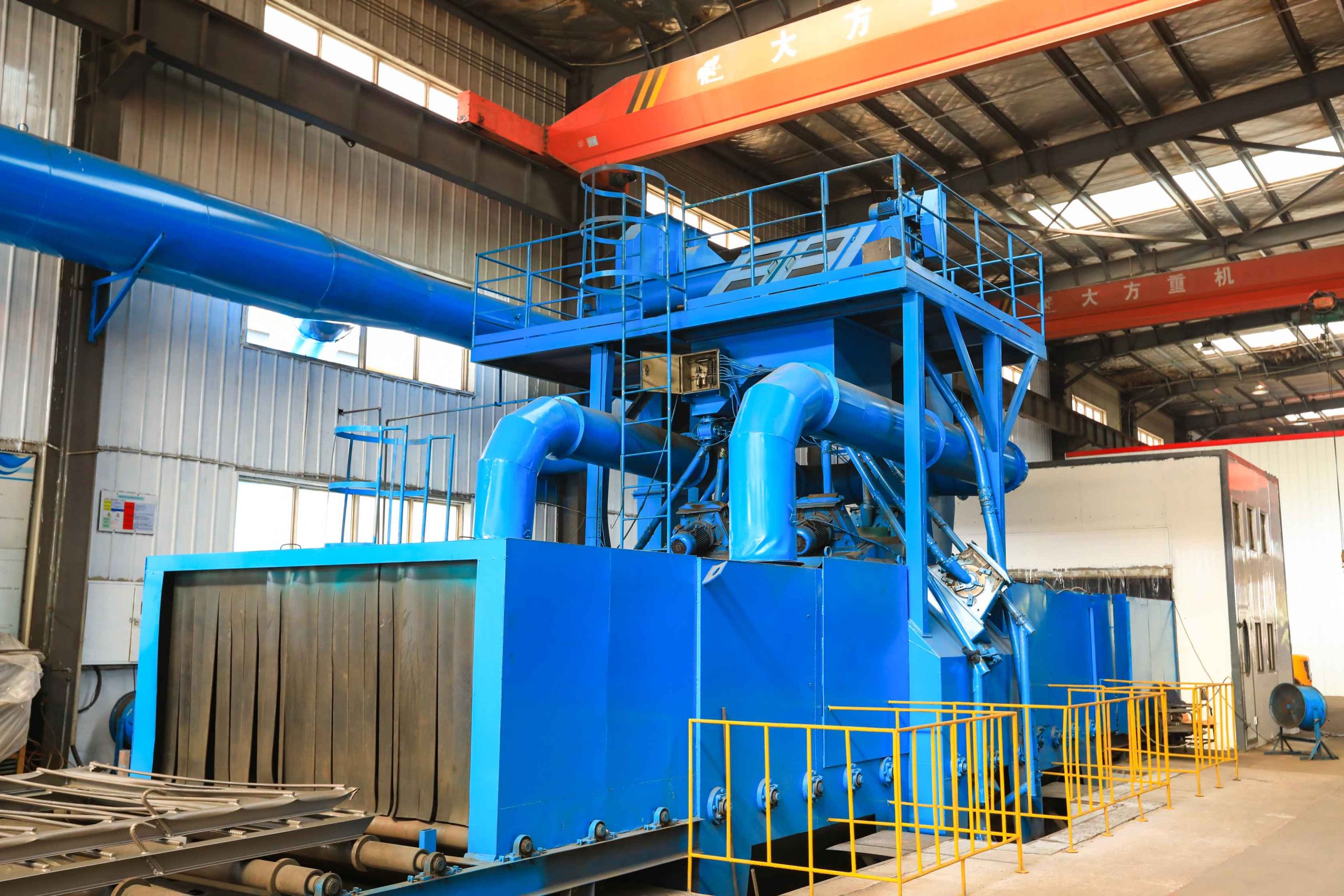
通过式抛丸机
Surface Treatment Procedures (Continued):
Sandblasting (Profile Consistency)
Common Product Issue:
Insufficient Sa 2.5 coverage on the flange edges of H-beams (<90%).
Root Cause:
Media rebound reduces edge and corner coverage, especially on thick sections (>40 mm).
Solution:
-
Mixed Media: 80% steel shot (S230) + 20% angular garnet (G18).
-
Optimized Robotic Nozzle: Achieve a 45° impact angle with a movement speed of 30 cm/s.
-
Real-time Monitoring: Use a laser profilometer to verify 50-75 μm Ra roughness.
Coating Application (Sagging/Pinhole Defects)
Common Product Issue:
Epoxy resin sagging on large plates (6×20 meters) with a coating thickness (DFT) >200 μm.
Root Cause:
High viscosity (greater than 90 KU at 25°C) results in poor atomization.
Solution:
-
Modify Coating: Add 2% fumed silica to increase thixotropy.
-
Upgrade Equipment: Use Graco XHD 790 airless spray gun (pressure ratio 30:1).
-
Environmental Control: Maintain substrate temperature between 15-35°C, with relative humidity under 85%.
Complex Geometries (Truss Structures)
Common Product Issue:
Uneven DFT (±40%) inside Φ600mm tubular joints.
Solution:
-
Rotating Fixtures: Achieve 360° coverage at 5-8 RPM.
-
Endoscopic-Assisted DFT Measurement: Use DeFelsko PosiTector UTG for accurate readings.
-
Quick-Curing Epoxy: Use a fast-curing epoxy with 25-minute no-tack time to prevent sagging.
Quality Traceability
Common Issue:
Coating failures cannot be traced back to production batches.
Solution:
-
Laser Marking: Mark batch ID on non-coated areas.
-
Test Plates Archiving: Archive test plates (100×100 mm) for 5 years.
-
Blockchain Record: Record process parameters (sensor accuracy ±1%) using blockchain for secure traceability. Key Metrics
The focus on achieving consistent profiles, preventing defects like sagging or pinholes, and ensuring traceability is essential to maintaining quality across large projects and complex geometries. These processes and solutions ensure coatings meet required standards while offering durability and longevity.
| Problem Type | Traditional Defect Rate | Optimized Defect Rate | Cost Impact |
|---|---|---|---|
| Edge Coverage | 18% | 4% | +7% |
| Coating Bubbles | 12% | 2% | +5% |
| Salt Contamination | 9% | 0.5% | +9% |
Results:
After process improvements, the Overall Equipment Efficiency (OEE) increased from 65% to 82%, the rework rate dropped to <1.5%, and ISO 12944 durability standards were achieved.
If you are interested in the above solutions, feel free to contact us. Our professional technicians are ready to assist you!
